|


| Quantity: | |
|---|---|
YT-25
WINCOO
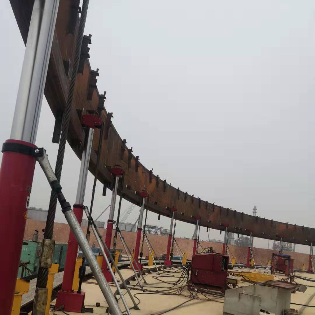
The hydraulic jacks is mainly used in the inverted construction of vertical cylindrical steel storage tank (hydraulic jacking method) and inverted construction of vertical cylindrical low temperature storage tank.
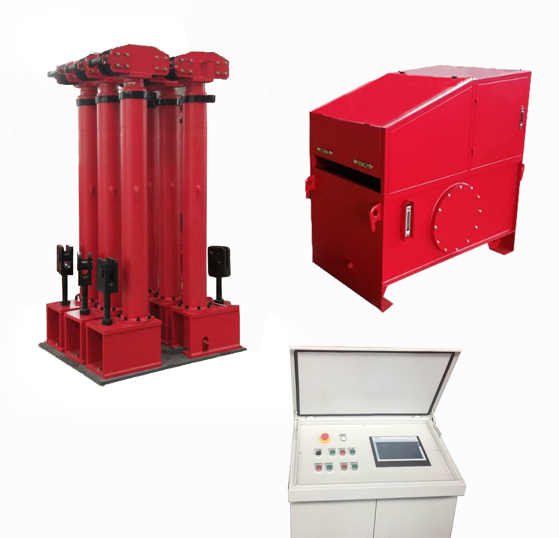
I. Electrical control system: power distribution box, centralized control box (operation table) and pump station control box.

Power Distribution Box

Centralized Control Box

Pump Station Control Box
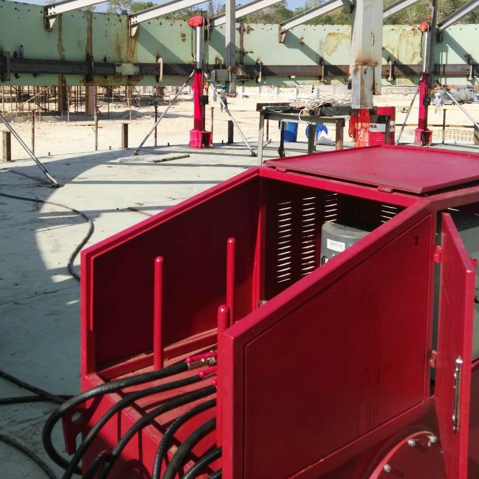
II. Hydraulic control system: hydraulic jacking pump station, high pressure ball valve, high pressure hose and oil tank, etc.
III. Jacking hydraulic cylinder: hydraulic cylinder, wire rope, such as rod device, hydraulic cylinder roof device, hydraulic cylinder support rod, etc.

The hydraulic jacks is suitable for use in the actual environment and operating conditions specified below.
A. Ambient air temperature; The range is -10℃ to 60℃;
B. Keep the installation location away from inflammable and explosive materials;
I. Overall structure and working principle
A. Overall structure
1, The equipment is uniformly placed around the object to be lifted. The overall force and lateral force of the equipment have been strictly calculated and successfully applied.
2, The structure is rigorous and compact, the output force is adjustable, the lifting speed meets the lifting requirements, and the synchronization accuracy is high.
B. Overall working principle
1, Force transmission process:Output force of hydraulic cylinder → Wire rope → Expansion ring (lifting lug) → Conducting plate → Wall plate lifting;
2, Jacking control process:Pump station control box (rotate selection button) → centralized control operation box (Figure 1-3) → Hydraulic jacking pump station (electromagnet of valve set) → isogenous device (isogenous contact) → centralized control operation box → hydraulic jacking pump station → whole or part of hydraulic cylinder lift and drop;
or
Pump station control box (rotate selection button) → control handle → hydraulic cylinder (single or multiple) fine-tune the lift and fall;
II. The function and working principle of the main components
A. The oil tank is a closed tank, which contains hydraulic oil and provides the oil source for the equipment.
1, The liquid level gauge shows the oil level and liquid temperature in the tank;
2, Air filter is the gas protection of hydraulic oil and air purification;
3, The lifting lug is used for lifting equipment;
4, Oil drain plug is convenient for equipment maintenance or replacement of hydraulic oil;
B. The hydraulic system is the power source for the entire hydraulic lifting equipment.
The plunger pump is driven by a motor, and the mechanical energy of the pump is converted into pressure energy, which is sent to an actuator (hydraulic cylinder) through a pressure valve (overflow valve) and a direction valve (electromagnetic valve) to be converted into mechanical energy to drive a load.
1, The protective cover can be disassembled, mainly protecting all parts under the cover;
2, The electromagnetic reversing valve completes the lifting and lowering actions of the hydraulic cylinder through the power gain and loss of the electromagnet;
3, The relief valve controls the pressure of the system to maintain constant by adjusting the handle of the relief valve so as to realize the functions of pressure regulation, pressure stabilization, or pressure limitation (preventing overload); the clockwise rotation indicates pressure going up while the reverse indicates going down. See Figure 1-8 Hydraulic Control Section;

4, The set range of relief valve for this set of equipment (0-31.5MPa);
5, The pressure gauge shows the pressure value of the system;
6, The high-pressure ball valve allows the hydraulic oil in the system to circulate or cut off;
7, This valve is mainly used for safety protection in this set of equipment. During the actual operation and application of the equipment, the handle of the high-pressure ball valve is rotated to control the flow or cut-off of hydraulic fluid;

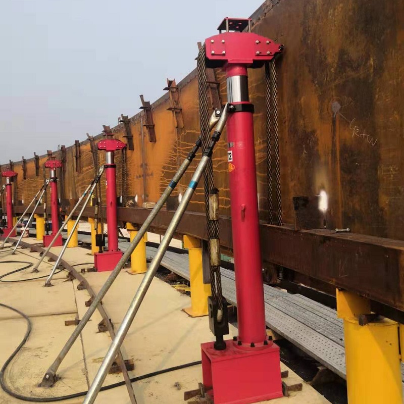
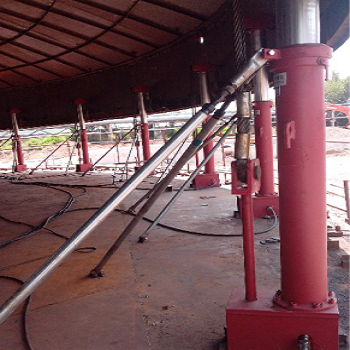
C. Hydraulic jack section

1, The hydraulic cylinder is an actuator with a rated output force of 300kN;
2, The cylinder head and supporting device of the hydraulic cylinder are the force bearing points of the rod end of the piston rod of the hydraulic cylinder. The purpose is to prevent the cylinder from being damaged, even invalid, and safety accidents caused by bending of the piston rod during the lifting of the tank body;Through the aligning and stop points set in the control section, the equipment can run synchronously when lifting the storage tank and stop running at the designated set position
3, The hydraulic cylinder supporting and adjusting lever is mainly used to meet the requirements of resistance to wind load and unbalance loading of the tank body during the lifting process of the tank body, and can also assist in setting the clearance between the hydraulic cylinder roof device and the tank wall when having the piston ring falling after rise;
4, The equal rod aligning device ensures synchronization and stop of lifting position when lifting the storage tank;
5, Through the aligning and stop points set in the control section, the equipment can run synchronously when lifting the storage tank and stop running at the designated set position;
6, The one-way explosion-proof valve is a safety valve to make the hydraulic cylinder self-lock. During the lifting process of the storage tank or during the suspended construction process of the storage tank, the tank body will not slide down or fall down due to sudden explosion, blurting out, sudden power failure and the like of the high-pressure rubber hose.
Max service pressure | Max output force of single hydraulic cylinder | Max stroke of hydraulic cylinder | Hydraulic cylinder lifting speed | Oil pump flow | Motor speed | Motor voltage | Motor power | Working environment temperature | |
YT10-2200C | 24Mpa | 10T | 1250mm | 190mm/min | 14.4L/min | 1440r/min | ~380V | 5.5kw | -15~50 ℃ |
YT10-2700C | 31Mpa | 10T | 1400mm | 270mm/min | 7.2L/min | 1440r/min | ~380V | 5.5kw | -15~50 ℃ |
YT12-2700C | 31Mpa | 12T | 1400mm | 250mm/min | 7.2L/min | 1440r/min | ~380V | 5.5kw | -15~50 ℃ |
YT18-1700C | 24Mpa | 18T | 1240mm | 175mm/min | 7.2L/min | 1440r/min | ~380V | 4kw | 0~50℃ |
YT18-2000C | 24Mpa | 10T | 1240mm | 175mm/min | 7.2L/min | 1440r/min | ~380V | 4kw | 0~50℃ |
YT18-3000C | 25Mpa | 18T | 1600mm | 187mm/min | 7.2L/min | 1440r/min | ~380V | 5.5kw | -10~60℃ |
YT25-2700C | 31.5Mpa | 25T | 1650mm | 175mm/min | 7.2L/min | 1440r/min | ~380V | 5.5kw | -10~60℃ |
YT25-3000C | 29Mpa | 25T | 3200mm | 160mm/min | 7.2L/min | 1440r/min | ~380V | 4kw | -10~60℃ |
YT30-2700C | 29Mpa | 30T | 2050mm | 130mm/min | 7.2L/min | 1440r/min | ~415V | 4kw | -10~60℃ |